accessories electrical
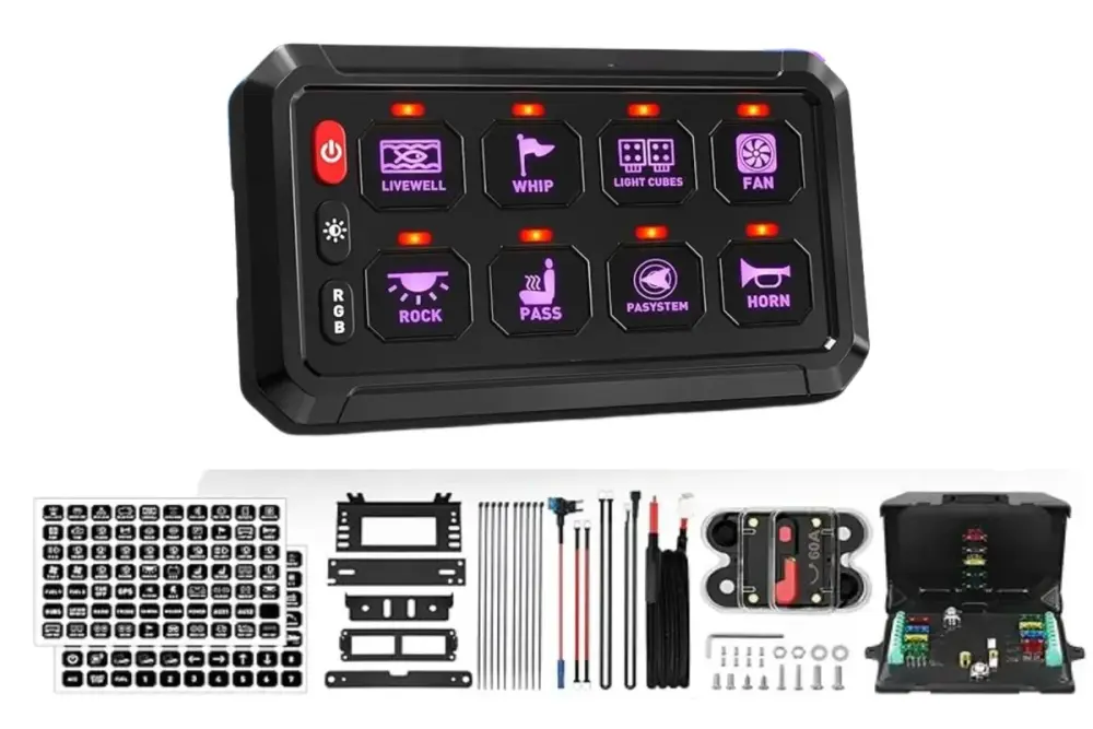
8 Gang Switch Panel Kit
8 Gang switch panel for 12-24V vehicles. 60A rated, 1,200W max. Plug-and-play with reverse polarity & thermal protection.
$169.99
 Authorized RNG DealerAuthorized RNG Performance Dealer· 2-3 day shipping from Cincinnati· Don't see your part? Call 513-458-9614
Published July 8, 2025
A typical UTV turn signal kit includes front and rear LED turn signal lights, a flasher relay (turn signal module), a toggle or stalk switch for the driver, a wiring harness, and mounting hardware. Higher-quality kits also include a horn button and brake light integration. Before purchasing, verify that the kit is compatible with your UTV's voltage system (most UTVs are 12V) and that the mounting hardware fits your specific model's roll cage or body panel dimensions.
If you plan to add other electrical accessories alongside your turn signals, light bars, rock lights, a winch, or a heater, consider installing a dedicated switch panel at the same time. The RNG 8-gang switch panel kit provides eight individually fused and relay-protected circuits, which makes wiring turn signals and other accessories much cleaner than splicing into factory harnesses. You can dedicate one circuit to the turn signal flasher relay and have seven remaining for other accessories.
Turn signal circuits are straightforward. The basic circuit flows from the battery (through a fuse) to the flasher relay, then from the flasher relay to the turn signal switch, and from the switch to the individual lights. The flasher relay is what makes the lights blink, it interrupts the circuit at a set frequency, typically 60-90 flashes per minute.
Most kits use a three-wire system at each light: one wire for power (left or right signal), one for ground, and optionally one for a running-light function. The flasher relay typically has three terminals: power input (B+), left output (L), and right output (R). The switch connects between the relay outputs and the lights, selecting left, right, or off.
Use appropriate gauge wire for the circuit, 18 AWG is sufficient for LED turn signals. Use 16 AWG if you are running incandescent bulbs, which draw more current. All connections should be soldered and heat-shrunk or use marine-grade waterproof connectors. Do not use scotch-lock tap connectors or wire nuts, they corrode, vibrate loose, and fail in the wet and dusty conditions UTVs operate in.
Begin by planning your wire routing. Run wires along existing harness paths, inside frame rails, or along the roll cage using UV-resistant zip ties. Avoid routing near exhaust components, sharp edges, or moving parts like suspension components and steering linkages.
Before buttoning everything up, test the system. Turn on the ignition and activate each turn signal direction. Verify that the correct lights flash, front-left and rear-left together, front-right and rear-right together. Check the flash rate, it should be a steady, consistent blink. If the lights stay solid (no flashing), the flasher relay may not be compatible with your LED lights. LED-specific flasher relays are required for LED bulbs because LEDs draw very little current, which can cause standard thermal flasher relays to malfunction.
If adding a hazard function, verify that all four lights flash simultaneously when the hazard switch is activated. Test the horn if your kit includes one. Take the vehicle for a short drive and verify that vibration does not cause any connections to come loose or any lights to flicker.
Street-legal UTV registration requirements vary significantly by state. Most states that allow UTV road use require, at minimum: headlights, tail lights, brake lights, turn signals, a horn, mirrors, and a slow-moving vehicle (SMV) emblem or reflective triangle. Some states also require a windshield, seat belts (which UTVs typically have), and DOT-approved tires.
Check your specific state's DMV or motor vehicle authority for the exact requirements. Some states restrict UTVs to roads with speed limits of 35 mph or less, while others allow highway use. Insurance requirements also vary. Having a properly installed turn signal kit with a horn is the baseline for street-legal compliance in nearly every state that permits UTV road use.
Even if you do not plan to register your UTV for road use, turn signals are a valuable safety feature for trail riding, especially in group rides, on shared-use trails, and in low-visibility conditions. Signaling your intentions to other riders prevents accidents.
accessories electrical
8 Gang switch panel for 12-24V vehicles. 60A rated, 1,200W max. Plug-and-play with reverse polarity & thermal protection.